Showing posts with label Notes. Show all posts

Thursday, January 1, 2015

Link State Routing

Every node knows how to reach its directly connected neighbors, and if we make sure that the totality of this knowledge is disseminated to every node, then every node will have enough knowledge of the network to determine correct routes to any destination.

 Reliable Flooding is the process of making sure that all the nodes participating in the routing protocol get a copy of the link-state information from all the other nodes. As the term " flooding" suggests, the basic idea is for a node to send its link-state information out on all of its directly connected links, with each node that receives this information forwarding it out on all of its link. This process continues until the information has reached all the nodes in the network. 
Link State Packet(LSP) contains the following information:
1.The ID of the node that created the LSP;
2. A list of directly connected neighbors of that node, with the cost of the link to each one;
3. A sequence number;
4. A time to live(TTL) for this packet.

Flooding works in the following way. When a node X receives a copy of an LSP that originated at some other node Y, it checks to see if it has already stored a copy of an LSP from Y. If not, it stores the LSP. If it already has a copy, it compares the sequence numbers; if the new LSP has a larger sequence number, it is assumed to be the more recent, and that LSP is stored, replacing the old one. The new LSP is then forwarded on to all neighbors of X except the neighbor from which the LSP was just received.

Each switch computes its routing table directly from the LSPs it has collected using a realization of Dijkstra's algorithm.

Every 10 S the average delay of all packets is computed.
( A longer measurement period = less adaptive routing if conditions actually change. A shorter measurement period = less optimal routing because of inaccurate measurement.) The delay is considered to have changed "by a significant amount" whenever the absolute value of the change exceeds a certain thershold. Threshold is a decreasing function of time. Threshold is decreased by 12.8 ms.

When the delay changes by only a small amount, it is not important routing changes. However, whenever a change in delay is long lasting, it is important that it should be reported eventually, even if it is small; otherwise, additive effects can introduce large inaccuracies into routing. A threshold value which is initially high but which decreases to zero over a period time has this effect. In this paper, the initial threshold is 64 ms. After each measurement period, the newly measured average delay is compared with the previously reported delay. If the difference does not exceed the threshold, the threshold is decreased by 12.8 ms. 

Whenever a change in average delay equals or exceeds the threshold, an update is generated, and the threshold is reset to 64 ms. Since the threshold will eventually decay to zero, an update will always be sent after a minute, even if there is no change in delay. 

Link state routing

A link-state routing protocol is one of the two main classes of routing protocols used in packet switching networks for computer communications (the other is the distance-vector routing protocol). Examples of link-state routing protocols include open shortest path first (OSPF) and intermediate system to intermediate system (IS-IS).

Wednesday, December 31, 2014

Distance-Vector Routing

 Each node constructs a one-dimensional array containing the "distances"(costs) to all other nodes and distributes that vector to its immediate neighbors.
1. The starting assumption for distance-vector routing is that each node knows the cost of the link to each of its directly connected neighbors.
2. A link that is down is assigned an infinite cost.
Example.
Information                                  Distance to Reach Node
Stored at Node              A      B      C     D     E      F        G

A                                    0        1       1      ?      1       1         ?

B                                     1        0       1      ?      ?       ?        ?

C                                    1          1       0      1     ?       ?        ?

D                                     ?         ?       1       0    ?        ?       1

E                                      1        ?       ?      ?      0      ?        ?

F                                      1         ?       ?        ?      ?      0      1

G                                     ?         ?     ?        1      ?       1       0

Table 1. Initial distances stored at each node(global view).


We can represent each node's knowledge about the distances to all other nodes as a table like the one given in Table 1. Note that each node only knows the information in one row of the table.
1.Every node sends a message to its directly connected neighbors containing its personal list of distance. ( for example, A sends its information to its neighbors B,C,E, and F. )

2. If any of the recipients of the information from A find that A is advertising a path shorter than the one they currently know about, they update their list to give the new path length and note that they should send packets for that destination through A. ( node Blearns from A that node E can be reached at a cost of 1; B also knows it can reach A at a cost of 1, so it adds these to get the cost of reaching E by means of A. B records that it can reach E at a cost of 2 by going through A.)

Tuesday, December 30, 2014

subnetting

A subnetwork, or subnet, is a logically visible subdivision of an IP network. The practice of dividing a network into two or more networks is called subnetting. All computers that belong to a subnet are addressed with a common, identical, most-significant bit-group in their IP address. This results in the logical division of an IP address into two fields, a network or routing prefix and the rest field or host identifier. The rest field is an identifier for a specific host or network interface.


For the purpose of network management, an IP address is divided into two logical parts, the network prefix and the host identifier or rest field. All hosts on a subnetwork have the same network prefix. This routing prefix occupies the most-significant bits of the address. The number of bits allocated within a Tnetwork to the internal routing prefix may vary between subnets, depending on the network architecture. While in IPv6 the prefix must consist of a set of contiguous 1-bits, in IPv4 this is not enforced, though there is no advantage to using non-contiguous 1-bits. The host part is a unique local identification and is either a host number on the local network or an interface identifier.

 This logical addressing structure permits the selective routing of IP packets across multiple networks via special gateway computers, called routers, to a destination host if the network prefixes of origination and destination hosts differ, or sent directly to a target host on the local network if they are the same. Routers constitute logical or physical borders between the subnets, and manage traffic between them. Each subnet is served by a designated default router, but may consist internally of multiple physical Ethernet segments interconnected by network switches or network bridges. 

The routing prefix of an address is written in a form identical to that of the address itself. This is called the network mask, or netrmask, of the address. For example, a specification of the most-significant 18 bits of an IPv4 address, 11111111.11111111.11000000.00000000, is written as 255.255.192.0. If this mask designates a subnet within a larger network, it is also called the subnet mask. This form of denoting the network mask, however, is only used for IPv4 networks. 

The modern standard form of specification of the network prefix is CIDR notation, used for both IPv4 and IPv6. It counts the number of bits in the prefix and appends that number to the address after a slash (/) character separator:
192.168.0.0, netmask 255.255.255.0 is written as 192.168.0.0/24 In IPv6, 2001:db8::/32 designates the address 2001:db8:: and its network prefix consisting of the most significant 32 bits. 
This notation was introduced with Classless Inter-Domain Routing (CIDR) In IPv6 this is the only acceptable form to denote network or routing prefixes

In classful networking in IPv4, prior to the introduction of CIDR, the network prefix could be directly obtained from the IP address, based on its highest order bit sequence. This determined the class (A, B, C) of the address and therefore the network mask. Since the introduction of CIDR, however, assignment of an IP address to a network interface requires two parameters, the address and its network mask. 

In IPv4, on-link determination for an IP address is given simply by the address and netmask configuration, as the address cannot be disassociated from the on-link prefix. For IPv6, however, on-link determination is different in detail and requires the Neighbor Discovery Protocol (NDP). IPv6 address assignment to an interface carries no requirement of a matching on-link prefix and vice versa, with the exception of link-local addresses. 

While subnetting may improve network performance in an organizational network, it increases routing complexity, since each locally connected subnet must be represented by a separate entry in the routing tables of each connected router. However, by careful design of the network, routes to collections of more distant subnets within the branches of a tree-hierarchy can be aggregated by single routes.Variable-length subnet masking (VLSM) functionality in commercial routers made the introduction of CIDR seamless across the Internet and in enterprise networks.

Thursday, December 25, 2014

Link Level Flow Control

Flow control is a technique that a transmitting entity does not conquer a receiving entity with data. Two fundamental mechanisms are acknowledgement and timeouts.
Ø  After getting each frame the receiver will send ACK to sender.
Ø  If the sender does not receive ACK up to reasonable amount of time then it retransmit the original frame waiting for reasonable amount of time is called timeout.
The two flow control mechanisms are
Ø  Stop and wait Flow Control
Ø  Sliding Window Flow Control
Stop and Wait Algorithm
Ø  After transmitting one frame, the sender waits for an                  acknowledgment before transmitting the next frame.

Ø  If the acknowledgment does not arrive after a certain period of time, the sender times out and retransmit the original frame.


            a) The ACK is received before
                  the timer expires    


 b) The original frame is lost


                        c) The ACK  is lost


d)The timeout fires too soon


Fig: illustrates four different scenarios that result from this basic algorithm. The sending side is represented on the left, the receiving side is depicted on the right, and time flows from top to bottom.

Ø  In Fig (a) ACK is received before the timer expires, (b) and (c) show the situation in which the original frame and the ACK, respectively, are lost, and (d) shows the situation in which the timeout fires too soon..
Ø  Suppose the sender sends a frame and the receiver acknowledges it, but the acknowledgment is either lost or delayed in arriving. This situation is in (c) and (d). In both cases, the sender times out and retransmit the original frame, but the receiver will think that it is the next frame, since it correctly received and acknowledged the first frame.
Ø  This makes the receiver to receive the duplicate copies. To avoid this two sequence numbers (0 and 1) must be used alternatively.


Ø  The main drawback of the stop-and-wait algorithm is that it allows the sender have only one outstanding frame on the link at a time.

Sunday, December 21, 2014

Error Detection and Correction

Data can be corrupted during transmission. For reliable communication, errors must be detected and corrected.

Types of Errors

Single-bit error

The term Single-bit error means that only one bit of a given data unit (such as byte, character, data unit or packet) is changed from 1 to 0 or from 0 to 1.
Burst Error
The term Burst Error means that two or more bits in the data unit have changed from 1 to 0 or from 0 to 1.
Redundancy
             One method is to send every data twice, so that receiver checks every bit of two copies and detect error.
Drawbacks
Ø  Sends n-redundant bits for n-bit message.
Ø  Many errors are undetected if both the copies are corrupted.
Instead of adding entire data, some bits are appended to each unit.
             This is called redundant bit because the bits added will not give any new information. These bits are called error detecting codes.
The three error detecting techniques are:
Ø  Parity check
Ø  Check sum algorithm
Ø  Cyclic Redundancy Check
Parity Check
Simple parity check
             Only one redundant bit, called parity bit is added to every data unit so that the total number of 1’s in unit become even (or odd)
Two Dimensional Parity
Ø  It is based on simple parity.
Ø  It performs calculation for each bit position across each byte in the frame.
Ø 


This adds extra parity byte for entire frame, in addition to a parity bit for each byte.

            For example frame containing 6 bytes of data. In this third bit of the parity byte is 1 since there are an odd number of 1’s is in the third bit across the 6 bytes in the frame.
            In this case, 14 bits of redundant information are added with original information.

Check sum algorithm
Ø  In the sender side all the words are added and then transmit the result of sum called checksum with the data.
Ø  The receiver performs the same calculation on the received data and compares the result with the received checksum.
Ø  If any transmitted data, including the checksum itself, is corrupted, then the results will not match, so the receiver knows that an error occurred.
 Ø  Instead of sending the checksum as such, one’s complement of that sum will be send to the receiver. If the receiver gets the result as zero then it will be the correct one.
Ø  In this, we can represent unsigned number from 0 to 2n using n bits.
Ø  If the number has more than n bits, the extra leftmost bits need to be added to the n rightmost bits.
Ø  Data can be divided in to 16 bit word and the Checksum is initialized to zero.


Saturday, December 20, 2014

Issues in the data link layer

Framing
          To transmit frames over the node it is necessary to mention start and end of each frame. There are three techniques to solve this frame
Ø  Byte-Oriented Protocols (BISYNC, PPP, DDCMP)
Ø  Bit-Oriented Protocols (HDLC)
Ø  Clock-Based Framing (SONET)
Byte Oriented protocols
              In this, view each frame as a collection of bytes (characters) rather than a collection of bits. Such a byte-oriented approach is exemplified by the BISYNC (Binary Synchronous Communication) protocol and the DDCMP (Digital Data Communication Message Protocol)
Sentinel Approach

          The BISYNC protocol illustrates the sentinel approach to framing; its frame format is 
Ø  The beginning of a frame is denoted by sending a special SYN (synchronization) character.
Ø  The data portion of the frame is then contained between special sentinel characters: STX (start of text) and ETX (end of text).
Ø  The SOH (start of header) field serves much the same purpose as the STX field.
Ø  The frame format also includes a field labeled CRC (cyclic redundancy check) that is used to detect transmission errors.
          The problem with the sentinel approach is that the ETX character might appear in the data portion of the frame. BISYNC overcomes this problem by “escaping” the ETX character by preceding it with a DLE (data-link-escape) character whenever it appears in the body of a frame; the DLE character is also escaped (by preceding it with an extra DLE) in the frame body. This approach is called character stuffing.

Point-to-Point Protocol (PPP)
                  The more recent Point-to-Point Protocol (PPP). The format of PPP frame is
Ø  The Flag field has 01111110 as starting sequence.
Ø  The Address and Control fields usually contain default values
Ø  The Protocol field is used for demultiplexing.
Ø  The frame payload size can he negotiated, but it is 1500 bytes by default.
Ø  The PPP frame format is unusual in that several of the field sizes are negotiated rather than fixed.
Ø  Negotiation is conducted by a protocol called LCP (Link Control Protocol).
Ø  LCP sends control messages encapsulated in PPP frames—such messages are denoted by an LCP identifier in the PPP Protocol.

Byte-Counting Approach
The number of bytes contained in a frame can he included as a field in the frame header. DDCMP protocol is used for this approach. The frame format is 

Ø  COUNT Field specifies how many bytes are contained in the frame’s body.

Ø  Sometime count field will be corrupted during transmission, so the receiver will accumulate as many bytes as the COUNT field indicates. This is sometimes called a framing error.
Ø  The receiver will then wait until it sees the next SYN character.

Bit-Oriented Protocols (HDLC)

 In this, frames are viewed as collection of bits. High level data link protocol is used. The format is 

Ø  HDLC denotes both the beginning and the end of a frame with the distinguished bit sequence 01111110.

Ø  This sequence might appear anywhere in the body of the frame, it can be avoided by bit stuffing.
Ø  On the sending side, any time five consecutive 1’s have been transmitted from the body of the message (i.e., excluding when the sender is trying to transmit the distinguished 01111110 sequence), the sender inserts a 0 before transmitting the next bit.
Ø  On the receiving side, five consecutive 1’s arrived, the receiver makes its decision based on the next bit it sees (i.e., the bit following the five is).
Ø  If the next bit is a 0, it must have been stuffed, and so the receiver removes it. If the next bit is a 1, then one of two things is true, either this is the end-of-frame marker or an error has been introduced into the bit stream.
Ø  By looking at the next bit, the receiver can distinguish between these two cases:
7     If it sees a 0 (i.e., the last eight bits it has looked at are 01111110), then it is the end-of- frame marker.
8     If it sees a 1 (i.e., the last eight bits it has looked at are 01111111), then there must have been an error and the whole frame is discarded.

Friday, December 19, 2014

Fiber Optic Cable

Fiber Optic Cable
A fiber-optic cable is made of glass or plastic and transmits signals in the form of light.
Properties of light
Ø  Light travels in a straight line as long as it moves through a single uniform substance. If traveling through one substance suddenly enters another, ray changes its direction.
Bending of light ray
If the angle of incidence(the angle the ray makes with the line perpendicular to the interface between the two medium) is less than the critical angle the ray refracts and move closer to the surface.
If the angle of incidence is equal to the critical angle, the light bends along the interface.
If the angle of incidence is greater than the critical angle, the ray reflects and travels again in the denser substance. Critical angle differs from one medium to another medium.
Optical fiber use reflection to guide light through a channel.

A Glass or plastic core is surrounded by a cladding of less dense glass or plastic.

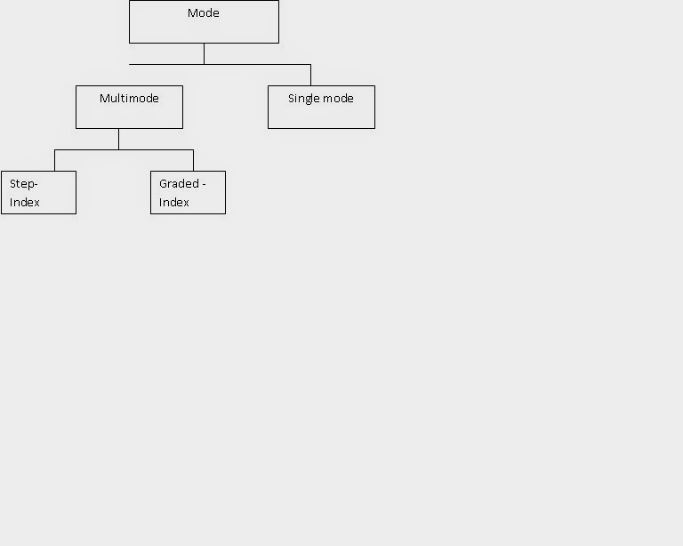
Propagation Modes
Multimode
In the multiple mode, multiple light beams from a source move through the core in different paths.
Ø  Multimode-Step-Index fiber: The density of core remains constant from the centre to the edge.
A ray of light moves through this constant density in a straight line until it reaches the interface of the core and the cladding. At the interface there is an abrupt change to a lower density that changes the angle of the beam’s motion.
Ø  Multimode- Graded -Index fiber: The density is varying. Density is highest at the centre of the core and decreases gradually to its lowest at the edge.
Single Mode
Single mode uses step-index fiber and a highly focused source of light
that limits beams to a small range of angles, all close to the horizontal.
The single mode fiber itself is manufactured with a much smaller
diameter than that of multimedia fiber.
Connectors
Ø  Subscriber channel (SC) connector  is used for cable TV.
Ø  Straight-tip (ST) connector is used for connecting cable to networking devices.