
Showing posts with label 8051 MICROCONTROLLER. Show all posts
Showing posts with label 8051 MICROCONTROLLER. Show all posts
Friday, March 28, 2014

Tuesday, February 25, 2014
8051 MICROCONTROLLER
8051 is an excellent device for building many embedded systems. One important factor is that the 8051 requires a minimum number of external components in order to operate.
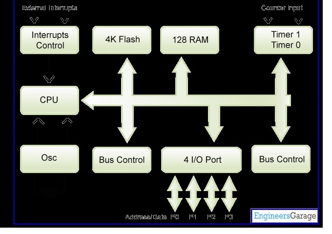
It is a well-tested design; introduced in its original form by Intel in 1980 the development costs of this device now start at less than US $1.00. At this price, you get a performance of around 1 million instructions per second, and 256 bytes (not megabytes!) of on-chip RAM, 32 port pins and a serial interface. Features of 8051: The main features of 8051 microcontroller are: RAM – 128 Bytes (Data memory) ROM – 4Kbytes . Serial Port – Using UART makes it simpler to interface for serial communication. Two 16 bit Timer/ Counter, Input/output Pins – 4 Ports of 8 bits each on a single chip. 6 Interrupt Sources 8 – bit ALU (Arithmetic Logic Unit)Harvard Memory Architecture – It has 16 bit Address bus (each of RAM and ROM) and 8 bit Data Bus. 8051 can execute 1 million one-cycle instructions per second with a clock frequency of 12MHz. This microcontroller is also called as “System on a chip” because it has all the features on a single chip. The Block Diagram of 8051 Microcontroller is as shown in Figure
Pin configuration of 8051
The following is the Pin diagram of 8051 microcontroller.

PIN 9: PIN 9 is the reset pin which is used to reset the microcontroller’s internal registers and ports upon starting up. (Pin should be held high for 2 machine cycles.) PINS 18 & 19: The 8051 has a built-in oscillator amplifier hence we need to only connect a crystal at these pins to provide clock pulses to the circuit. PIN 40 and 20: Pins 40 and 20 are VCC and ground respectively. The 8051 chip needs +5V 500mA to function properly, although there are lower powered versions like the Atmel 2051 which is a scaled down version of the 8051 which runs on +3V. PINS 29, 30 & 31: As described in the features of the 8051, this chip contains a built-in flash memory. In order to program this we need to supply a voltage of +12V at pin 31. If external memory is connected then PIN 31, also called EA/VPP, should be connected to ground to indicate the presence of external memory. PIN 30 is called ALE (address latch enable), which is used when multiple memory chips are connected to the controller and only one of them needs to be selected. PIN 29 is called PSEN. This is "program store enable". In order to use the external memory it is required to provide the low voltage (0) on both PSEN and EA pins.
Subscribe to:
Posts (Atom)